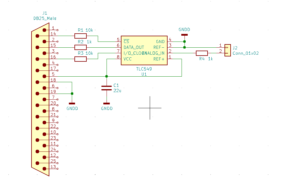
For my experiments with the temperature sensors LM35/LM335 I needed an ADC to connect them with my computer.
You also can use it to measure other analog signals.
Why LPT and not COM or USB?
I wanted to design a board that fits inside the connector.
For the COM-Port I would need a MAX232 Chip to bring the signals to a TTL level (LPT already has that). And the board was not large enough for another chip and the additional circuits for it. USB has the same problem, and it makes no sense to build a USB-Board into a SUB-D connector housing.
The next one maybe will be for the COM-Port with SMD and double-sided PCB.
The first test on a breadboard.
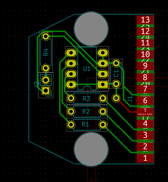
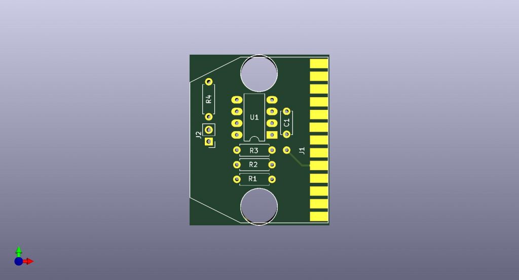
Board design
The hardest work was to measure the connector shell so the board will fit in
and to bring the solder pads for the connector to the right size and position.
I never etched the board. Next time when I have more and not just one board.
Or I will order it online. I have always wanted to try that.
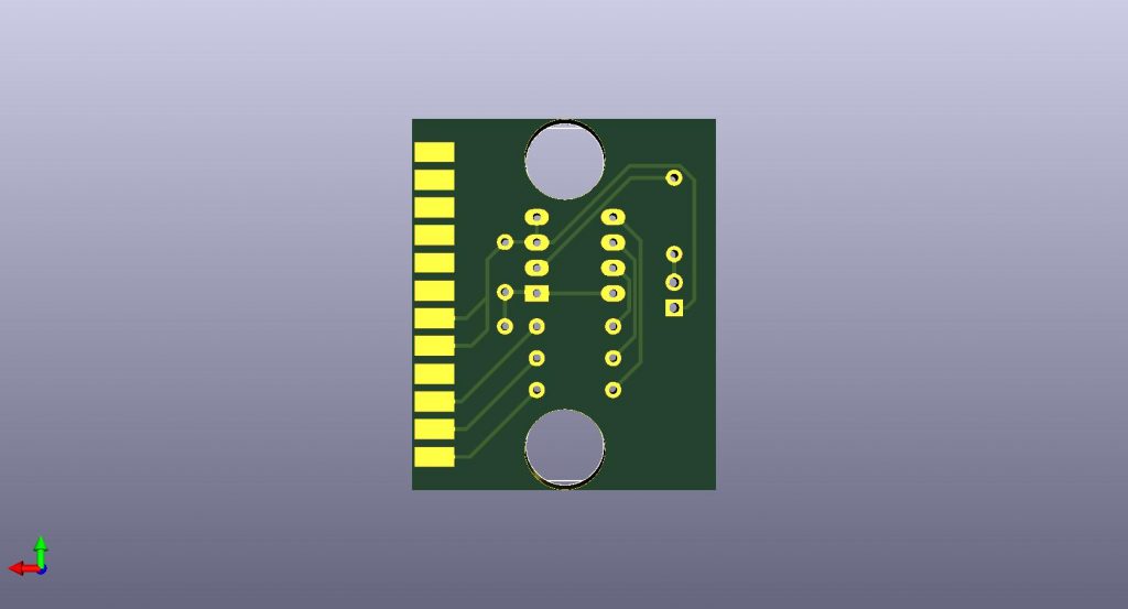
If you want to etch the board on your own, you don’t need a doble sided board.
It is possible to use a single layer copper board. The pins on the top are not used beside pin 5. Use a short wire to connect the pin 5 with the unused hole next to it.
Software for DOS
Schematic, layout and software. (Download-Link)
Leave a Reply